Pertronic Analogue Addressable Loop Length Calculator | |||
|
Please Enter Site Infomation (optional). Loop Number:
Site Name:
Site Address: Site Address1: Notes: | |||
| Items | No of units | Unit Current |
Total Quiescent Current |
| Loop Relay | 6 mA | 0 mA | |
| Loop Responder (Loop Powered) | 27 mA | 0 mA | |
| Loop Responder (Ext Powered) | 7 mA | 0 mA | |
| Conventional Smoke Detectors ++ | 0.05 mA | 0 mA | |
| Analogue Modules | 0.35 mA | 0 mA | |
| Analogue Detectors (F100A = 99 max) | 0.35 mA | 0 mA | |
| Isolate Timer Module | 10 mA | 0 mA | |
| PS2 Sounder 24V | 0.004 mA | 0 mA | |
| Alarm Acknowledge Module | 1.2 mA | 0 mA | |
| Fan Controller, Fan Relay | 0 mA | 0 mA | |
| PSB Sounder (F100A = 99 max) | 1.5 mA | 0 mA | |
| BSO-DD-N34 Base Sounder | 0.11 mA | 0 mA | |
| BEAM200S / 6500S Analogue Beam | 0 mA | 0 mA | |
| Enter alarm current in mA. (1 detector = 6.5 mA) | |||
| Total Current = TQmax | Load OK | 65 mA | |
| Twisted Pair Cable Size mm2 | |||
| Maximum Loop Current: MUST NOT Exceed | 350 mA | ||
| Minimum Panel Loop Voltage | 22.8 Volts | ||
| Minimum Working Loop Voltage | 15 Volts | ||
| Maximum Loop Volt Drop = VD | 7.8 Volts | ||
| Cable Resistance Ω/m | 0.021 Ω/m | ||
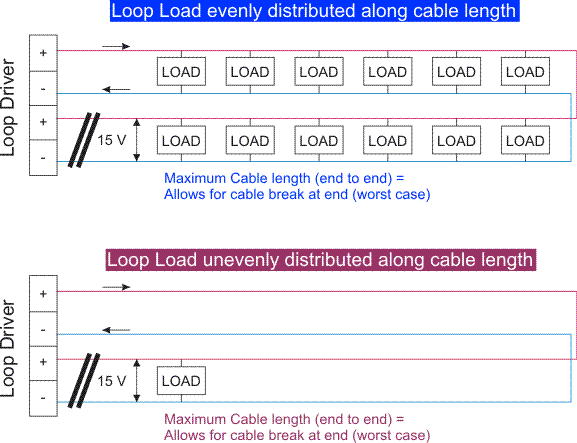
| Maximum Allowable Loop Cable Resistance, Load Spread Evenly = 2 x (VD/TQmax) ** | 50 Ω | ||
| Maximum Allowable Loop Cable Resistance, Load at end = VD/TQmax ** | 50 Ω | ||
| Maximum Cable Loop Length Must Not Exceed | 2500 Meters | ||
| Maximum Loop Length (m) - Load Spread Evenly Over Loop | 2500 Meters | ||
| Maximum Loop Length (m) - Load at end of Loop | 2500 Meters | ||
** To measure Analogue Loop Cable Resistance: a) short the cable pair at one end. b) bypass all isolators to ensure continuity (link +ve in to +ve out). c) measure the resistance across the two conductors - red to black. | |||
++ Include only Conventional Smoke Detectors connected to Loop Powered Interfaces such as Loop Responders. | |||
2500 m 2500 m 65 mA 65 mA  | |||