 CLICK to CALL US NOW

News
Purpose-Built Control & Indicating Boards for Sydney’s M4 East Motorway
Tweet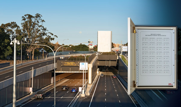
A few months after the opening of Sydney’s M4 East Motorway Tunnel, we were asked to supply remote control equipment for the tunnel fire hydrant system.
The new control equipment would enable tunnel operations staff to isolate sections of the hydrant system. For example, if a hydrant were damaged, the section containing the damaged hydrant could be isolated using the Pertronic FireMap® touch-screen graphical user interface. This would allow undamaged parts of the hydrant system to operate normally.
The consulting engineers specified an indicating board at the M4 East Motorway Control Centre, together with 26 control and indicating boards for installation at specific locations throughout the tunnel complex. Technical staff at our Lower Hutt factory and the local Australian office worked with the consulting engineers to develop detailed designs for the control and indicating boards.
Hydrant Isolation Control
The M4 East fire system is controlled by dual Pertronic FireMap® touch-screen graphical user interfaces (GUI). These GUIs were re-programmed with new diagrams and new virtual buttons to control the hydrant isolation valves via the tunnel’s F220/Net2 network.
Tunnel operators can choose from eight isolation options: Eastbound, Westbound, East Eastbound, West Eastbound, East Westbound, West Westbound, Eastern half, (East Eastbound & East Westbound), and Western half (West Eastbound & West Westbound). Each option activates a pre-defined set of valves to isolate the hydrants in the desired areas. FireMap provides visual confirmation when all selected valves are properly closed.
Local Isolation Valve Control and Indicating Boards
The 26 control and indicating boards (CIB) are housed in Pertronic 16U weatherproof cabinets. Each board communicates with an existing F220 fire panel via the F220’s analogue addressable signalling circuit (loop). In total there are 32 hydrant isolating valves; Some CIBs control two or three valves.

A Pertronic 24 Vdc 11 amp power supply inside each CIB supplies power for the control and indicating equipment, and the hydrant valve actuators. Each CIB also contains a sealed rechargeable back-up battery.
Production and Delivery
The design requirements were finalised on 1 October 2019. The indicator board and the CIBs were shipped from our factory between the 4th and 28th of November 2019. By the end of February 2020 the physical installation was complete and the CIBs were connected to mains power.
To complete the installation, each CIB had to be wired into an existing analogue addressable signalling circuit (loop). This work was scheduled for a maintenance close-down in early March.
Programming the System
The Pertronic F220/Net2 network at M4 East needed to be reprogrammed to implement the new control functions. The system has 97 network nodes and 93 fire panels. A new configuration programme must be loaded into each node and each fire panel.
This task is accomplished using a laptop computer running Pertronic FireUtils®. FireUtils® updates the entire system via a single connection in less than six minutes.
Custom Manufacturing
The M4 East hydrant isolation boards were designed around standard Pertronic modules. They were built by a production team who specialise in purpose-built equipment.
If your next project requires purpose-built control or indicating equipment, please contact your nearest Pertronic office to discuss your requirements.